Slag Analysis – Off-Line, At-Line, In-Line: A Guideline and Decision Support

Picture Source: Niloy Tanvirul
More than 90% of liquid steel produced today passes through a ladle furnace (LF) on its way to the caster. For modern steel grades — automotive sheet, linepipe, bearing steel, tire cord, spring steel, ULC IF — what happens in the ladle decides the final product. The LF is where sulfur is dropped to single-digit ppm, where dissolved oxygen is brought from hundreds of ppm down to a few, where alloy chemistry is set, and where the non-metallic inclusion population is engineered.
And yet, in most steelshops, LF slag chemistry is far less visible to the operator than EAF or BOF slag is. Historically, this lack of visibility was compounded by the absence of fast slag-analytics solutions — slag composition had to be inferred from process behavior, recipe, and experience, with confirmation arriving from the central lab only after the heat was well into the next stage. Even today, with rapid OES slag analysis available, the underlying metallurgical complexity remains: the slag does not foam in a way that betrays its composition. The arc is short and runs under a quiescent slag layer that, unlike EAF foam, does not respond visibly to chemistry shifts. There is no obvious visual signature for "too much FeO" or "MgO below saturation". The slag becomes a hidden variable — one that is sampled, sent to the lab, and reported back after the heat is well into the next stage. That is the starting position of this article: the LF is the highest-leverage point in the steelmaking chain for clean steel and ladle life, and at the same time the place where the slag is least visible during operation.
The variability of inputs to the ladle has grown, not shrunk, in the last decade:
- Mixed primary routes. A growing share of LF heats sit downstream of EAFs running on increasingly variable charge mixes — DRI/HBI, recycled secondary materials, alternative carbon sources — all of which change the chemistry of the tap slag and, by extension, the LF starting point. BOF carry-over has its own profile (high FeO, P₂O₅, lower Al₂O₃) and is, in some shops, the dominant feed; in any LF that sees both vessels, the operator must deal with two distinct starting chemistries.
- Tightening cleanliness specifications. Demand for low-S grades (≤ 20 ppm, often ≤ 10 ppm), engineered inclusion populations (Al₂O₃ inclusions modified to liquid calcium aluminates for castability; or deliberately retained MnO-SiO₂ silicates in long products) and reduced macro-inclusion rejects has moved the LF from "polishing step" to "core process unit".
- More vacuum treatment. VD and RH units are increasingly standard for clean grades, and their efficiency depends on the slag chemistry that arrives at the vacuum station — a point that will recur in this article.
- Carry-over slag from EAF or BOF tap is the largest single unknown. Reported values without intervention reach 10–15 kg per ton of steel, and even with a slag dart or pneumatic stopper the residual is typically 3–5 kg/t [1]. Both the mass and the composition of this carry-over vary heat to heat.
Recipe-based slag practice — "after tap, add X kg of lime, Y kg of synthetic flux, Z m of CaSi wire" — was workable in an era when no rapid slag-analytics solutions existed, the EAF/BOF tap was relatively consistent, and the cleanliness target was relaxed. It is no longer. The conditions inside the ladle drift, and without measurement they drift in the dark.
Companion piece: EAF Slag Optimization — The Tricky Balance" als Inline-Hinweis am Ende des Absatzes
The four competing objectives of LF slag management
A well-managed LF slag has to deliver on four jobs at the same time. As in the EAF, the levers controlling them are linked — but the linkages are different and, in some respects, tighter.
1. Refractory protection: CaO + MgO dual saturation
Ladle wear linings — usually MgO-C bricks at the slagline, doloma or doloma-C lower down — are protected when the slag is simultaneously saturated in MgO (against the magnesia component) and in CaO (against the lime component of the doloma). A common simplification is "MgO saturation protects the lining," but this is incomplete: in highly basic LF slags, the lowest slagline erosion is reached on the dual-saturation line (CaO + MgO), not at the MgO solubility limit alone. Below dual saturation in either component, the slag dissolves the corresponding refractory phase; above it, solid second phases appear in the slag and can also become problematic for fluidity and inclusion absorption. The fundamentals of this picture — developed for both EAF and LF slags — are summarized in the canonical work of Pretorius [2, 3], and extended for the LF doloma-C case by da Cruz and Bragança [4], who showed explicitly that the protective dicalcium silicate (C₂S) layer that forms on doloma-C bricks depends on the slag being saturated in CaO and on uncontrolled CaF₂ being avoided. Excessive fluorspar lowers slag viscosity and melting temperature, dissolves the C₂S layer, and accelerates corrosion. The "MgO saturation" framework alone misses this.
The practical consequence is that operating near dual saturation, with controlled CaF₂, is what the lining needs. Operating exactly at dual saturation is a moving target, because the saturation lines themselves shift with Al₂O₃, FeO and temperature. Tracking that moving target during operation is feasible only with slag composition feedback delivered within the heat — sample-prep-free OES slag analysis at sub-minute turnaround is the operational enabler.
2. Desulfurization: high basicity, high sulfide capacity, low FeO
Desulfurization is the LF's headline reaction. The thermodynamics ask for two conditions simultaneously: a slag with high sulfide capacity (C_S), and a low oxygen activity in the steel — the partition coefficient L_S = (%S)_slag / [%S]_steel scales with C_S and with 1/a_O. High C_S is reached by high basicity and high optical basicity (Λ), driven mainly by CaO; in conventional practice, CaF₂ improves slag fluidity and mass transfer, thereby enhancing desulfurization kinetics. Low a_O comes from killing with Al (or Si/Mn) and from keeping FeO and MnO in the slag low.
For Al-killed steels, the working range typically sits at B1 = CaO/SiO₂ > 5, with CaO 50–58%, Al₂O₃ 25–35%, SiO₂ < 8%, MgO 6–10% at saturation, and combined FeO + MnO below 1%, giving log C_S in the range of −1.5 to −2.0 [5]. Andersson et al. [6] reported on high-basicity ladle slags for bearing-steel production and quantified the sulfide capacity behavior across this composition range using KTH-style models. Pistorius and Piva [7] analyzed a large number of plant heats and showed that, regardless of slag composition, desulfurization is almost always rate-limited (kinetic), not capacity-limited (thermodynamic). A slag that looks fine on paper still under-performs if its composition drifts during the heat — fluidity falling, FeO returning from reoxidation, stirring too weak — because the reaction stalls in those windows and the lost time cannot be recovered in the 30–60 minute LF residence. What matters is keeping the slag in the right state throughout treatment, not just hitting the right composition at the end. This requires two or three samples per heat at a turnaround fast enough to act on each result — achievable in practice today with near-the-line LIBS systems that deliver chemistry in tens of seconds without sample preparation.
3. Inclusion engineering: the calcium-aluminate window
The third job is to engineer the non-metallic inclusion population. In Al-killed steel, primary deoxidation produces solid Al₂O₃ (corundum) inclusions — 2 050 °C melting, hard, abrasive, and the main cause of submerged-entry-nozzle (SEN) clogging during continuous casting. To prevent clogging, the standard practice is calcium treatment by CaSi-wire injection, which transforms the solid Al₂O₃ along the path
Al₂O₃ → CA₆ → CA₂ → CA → C₁₂A₇ (liquid at 1 415 °C)
via diffusion-controlled growth of a multi-phase aluminate product layer on the inclusion. Tabatabaei et al. [8] modeled this transformation explicitly and showed that calcium delivery from the wire is the rate-limiting step, but that the final endpoint — whether the inclusion ends up as a liquid C₁₂A₇ or as a partially-solid CA₂ — is set by steel-slag equilibrium, which in turn depends on the slag CaO activity and Al₂O₃ content. Yang et al. [9] confirmed this with industrial heats: the inclusion modification window is narrow, and slag chemistry drift moves the endpoint out of it.
The narrow window has two failure modes that meet in the middle:
- Under-modified inclusions: still solid CA₂/CA₆ or pristine Al₂O₃ → SEN clogging.
- Over-modified or wrong system: CaS forms on top of the modified aluminate, often as an outer ring, when the Ca activity is too high relative to the sulfur and dissolved oxygen levels — the resulting inclusion is again solid and again problematic.
A third trap is MgAl₂O₄ spinel formation, when Mg (from refractory or slag) reaches the inclusion before Ca does. Spinels are very stable and difficult to modify further. They form preferentially when the slag is too aggressive against the lining or too low in CaO. Pistorius [1] points out a non-obvious consequence: retaining a small amount of FeO + MnO in the ladle slag (a few percent, not zero) slows the transfer of dissolved Mg to the steel and delays spinel formation — a useful operating margin for some grades, but one that has to be measured to be sustained.
For Si-Mn-killed steel the picture is structurally different. The deoxidation product is MnO-SiO₂ (manganese silicate), which is liquid at steelmaking temperature and deformable during rolling — and therefore wanted, not modified out. The inclusion evolution path is
MnO-SiO₂-Al₂O₃ → MnO-SiO₂ → CaO-MnO-SiO₂ → CaO-SiO₂
with Al₂O₃ in the inclusion progressively reduced out by Mn/Si if the slag does not feed Al back in. Podder et al. [10, 11] modeled this case explicitly and demonstrated, with industrial Si-Mn killed heats, that the slag must be held at low basicity (B1 = 1.0–1.2) and Al₂O₃ < 5% to keep the inclusion population in the wanted MnO-SiO₂ region. A slag drifting toward higher Al₂O₃ (from EAF carry-over, from accidental Al-bearing additions, or from refractory reduction) will start feeding Al into the steel and switch the inclusion population from deformable silicate to undeformable alumina — the same SEN clogging problem, in a steel that was supposed to avoid it.
4. Reoxidation protection: low FeO + MnO into VD and casting
The fourth job is to keep the slag from reoxidizing the steel after it is killed. For shops with vacuum degassing (VD, VTD, RH), the slag covering the bath during evacuation must have FeO + MnO well below 1–2%, otherwise dissolved Al and Mg reduce these oxides at the slag-metal interface during stirring under vacuum, generating new alumina inclusions exactly when they are supposed to be floated out. The same logic applies during transfer to the tundish and during casting itself: low (FeO + MnO) protects against reoxidation along the entire chain downstream of the LF.
This is the operational frame in which the statement from Vid Vengust at Štore Steel about the use of an OES at-line slag analyzer makes sense: "With our new VD unit, controlling ladle slag online became crucial. Slag composition was often hard to predict, affecting process stability and degassing" [12]. Štore Steel produces Si-Mn killed spring and engineering steels — exactly the category in which slag-Al₂O₃ control and FeO+MnO suppression decide the inclusion fate during VD.

Two systems, not one: Al-killed vs Si-killed
The four objectives above hold for both Al-killed and Si-Mn-killed practice, but the slag compositions that meet them are fundamentally different. Treating LF slag as one system is a recurring error. The two systems are summarized below:
-jpg.jpeg?width=549&height=389&name=IMG-20260609-WA0004%20(002)-jpg.jpeg)
Two operational consequences follow. First, Si-Mn-killed steel typically requires higher flux additions than Al-killed — not because basicity is higher, but because the slag must dilute incoming Al₂O₃ from carry-over and from any Al-bearing additions, and because the deoxidation product itself (SiO₂) needs to be balanced into the slag without crossing the B1 = 1.2 line above which alumina inclusions start to dominate. Second, the sulfide capacity is lower in the Si-Mn system: the same desulfurization target requires a longer LF treatment, a larger slag mass, or a higher CaF₂ content — each of which has its own cost or constraint (CaF₂ accelerates refractory wear, larger slag mass means more carry-out to the next vessel).
A shop that runs both grade families on the same LF — common in long-products mills — is effectively running two different slag practices on the same equipment, with sample points and flux schedules that have to switch heat by heat. This is precisely the operating environment where the conventional slag analytics model — slow lab turnaround, with slag chemistry verified on only one or two of the eight to twelve heats produced per shift — can no longer keep up. The majority of heats run without any slag-side feedback at all.
Why it is tricky: the conflicts in detail
The carry-over problem: the unknown input
The LF starts every heat without knowing the mass or composition of the slag that came down with the tap. Pistorius [1] showed, with mass balances on aluminum and phosphorus across many heats, that the calculated impact of uncontrolled carry-over is severe: at typical tap slag composition (≈ 25% FeO+MnO, ≈ 0.25% P) and 10 kg/t carry-over, the deoxidation reaction alone requires roughly 0.5 kg Al/t of steel just to reduce the FeO and MnO that came in with the slag, and phosphorus reversion can reach 30 ppm in the steel — enough on its own to fail the spec on many grades. The conditioning step at the LF entrance exists precisely to deal with this unknown: it is impossible to design a fixed flux recipe for an unknown starting composition.
Prasad et al. [13] reported on operational practice at Rourkela Steel Plant: by modifying the deoxidation sequence (petroleum coke first, then aluminum during BOS tapping) and minimizing slag carry-over and downstream Al additions, total aluminum consumption was reduced by ≈ 30% to 4.2 kg/t of cast steel, while at the same time achieving cleaner steel. The savings are entirely a function of removing avoidable reactions in the ladle.
The Ca-treatment window is narrow, and it is set by the slag
The SAIL R&D study on a newly modernized BOF–twin-LF–slab-caster line at one of the integrated steel plants is one of the clearest published examples of how the slag controls the inclusion fate even when Ca-treatment is being applied. Kumar et al. [14] report that despite calcium treatment in every heat, the shop saw 28 sequence-casting aborts in a single month, with breaks already after 3–4 heats. Forensic analysis of the SEN deposits and process variables identified dendritic alumina clusters from reoxidation during secondary refining as the dominant cause. The Ca-treatment was nominally correct; the slag chemistry behind it was not. The fix required "optimization of Ca treatment practice" — which is shorthand for matching the Ca dosing to a measured, not assumed, slag and inclusion state. This is the operational consequence of the narrow modification window discussed in section 3 above.
The dual saturation tightrope
The MgO solubility surface in the LF slag system shifts with Al₂O₃, FeO and temperature. Almeida et al. [15] mapped this for the CaO-SiO₂-FeO-MgO-Al₂O₃ system at 1 600 °C, showing that the dual saturation point (C₂S + magnesiowüstite) moves substantially — the basicity at dual saturation goes from 2.15 at 0% Al₂O₃ to 2.78 at 8% Al₂O₃, and the FeO needed for dual saturation decreases as Al₂O₃ rises. In other words, the "right" MgO target is itself a function of the rest of the slag composition. For an LF charged from a variable EAF/BOF tap, the dual-saturation target moves heat by heat.
The conditioning step at the LF entrance
Because the input is unknown and the targets move, the standard solution is a conditioning step: take a slag sample immediately after tap (or at the LF entrance), determine the actual composition, and condition the slag with measured additions of burned lime, calcium aluminate flux or doloma to bring it to the operating window for the grade being made. A second sample partway through the LF verifies the conditioning, and a final sample at the end of the LF documents the result before transfer to VD or to the caster. The principle is simple, but only works if the analytical loop is fast enough that the additions arrive while the heat is still in the LF. With central-lab XRF turnaround of 10–15 minutes (preparation included), and an LF treatment time of 30–60 minutes, the first conditioning sample alone consumes a third or more of the total LF residence. Sample-prep-free OES slag analysis — granular slag sample, no melt-bead preparation, results in 20–30 seconds — collapses that latency. With it, the post-tap → conditioning → mid-LF → end-LF → pre-VD sequence fits comfortably inside the LF residence, and the conditioning loop closes for the first time.
The "insurance" problem, LF version
As in the EAF, operators who cannot see their slag fast enough run safety margins for "insurance" or "just-to-be-safe". In the LF the insurance is in two directions: over-fluxing (extra lime, extra calcium aluminate, extra CaF₂ — to cover the worst-case carry-over) and over-deoxidizing (extra Al, extra CaSi — to cover the worst-case dissolved oxygen and inclusion population). Both are expensive, and both also have side effects: over-fluxing increases slag mass and downstream carry-over; over-deoxidizing pushes the Ca-treatment closer to the CaS boundary on the wrong side of the liquid window.
From postmortem to process control
The shift from explanation-after-the-fact to in-heat control rests on analytical methods fast enough that a conditioning correction or a Ca-treatment adjustment arrives while the heat is still in the LF. As in EAF practice, several independent groups have arrived — from different technical starting points — at the same operating conclusion.
Multiple independent research groups have demonstrated, between 2014 and 2024, that the slag chemistry needed for in-heat conditioning can be measured in seconds, not minutes, near the line. Fraunhofer ILT (Aachen, 2014) installed a Laser OES (LIBS) system for 24/7 automatic analysis of liquid slag in the slag transporter ladle at Dillinger Hüttenwerke, quantifying the six oxides relevant to LF chemistry on hot slag (600–1 400 °C) at meters of standoff [16]. Swerim (Sweden, 2020 and 2023) built a near-the-line Laser OES system on a rotating sample holder and showed that machine-learning calibration improves accuracy for LF-relevant components over classical univariate methods [17, 18]. Tecnalia / ArcelorMittal Spain (2017) developed a hyperspectral reflectance regression method specifically for LF slag characterization, validated at ArcelorMittal Sestao with errors below 10% on major components and a reported process saving of 0.71 €/t of liquid steel on the LF side [19] — the most concrete published economic data point for an LF slag analytics deployment to date. Luxmet / University of Oulu (2020) demonstrated OES through the furnace roof, reading slag-related arc emission directly during the heat without physical sampling, and showed that CaF₂, MgO and MnO can be evaluated from spectra in an industrial ladle furnace [20, 21]. The Tenova-led iSlag project (RFCS-funded, 2020–2024) developed and field-tested a Laser OES slag analyzer with a machine-learning workflow, covering both EAF and LF slag at TenarisDalmine and at Sidenor Aceros Especiales Basauri [22].
Five independent technical paths — laser plasma on transported slag, laser plasma on a near-the-line sample, hyperspectral reflectance, in-furnace arc OES, and ML-enhanced spectral analysis — converging on the same answer: fast slag chemistry, near the line. The technical viability is no longer in question.
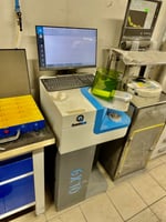
The step from research demonstration to routine plant operation has been carried by the next generation of sample-prep-free OES slag analyzers, most prominently the QuantoLux QLX9. In plant operation since 2024 and installed at nine steel mills worldwide, the QLX9 delivers slag analysis in roughly 20 seconds — about ten times faster than XRF — on granular slag, with no melt-bead preparation. The same platform covers EAF, BOF and LF slag analysis on a single instrument, which matters operationally in mixed-grade long-products mills where the slag practice switches heat by heat. At Štore Steel in Slovenia, the QLX9 is deployed specifically at the LF/VD slag interface for Si-Mn-killed spring and engineering steels — exactly the application category in which slag-Al₂O₃ control and FeO+MnO suppression decide the inclusion fate during VD [12, 23].
What rapid slag analysis actually delivers in practice (LF)
The point of fast analysis at the LF is not to replace one slow XRF sample with one fast LIBS sample. The point is to enable multiple samples per heat at the right points — post-tap, LF entrance after conditioning, mid-LF, end-LF, and (where present) pre-VD — so that the slag trajectory through the heat becomes visible and steerable, rather than only the endpoint.

In concrete terms:
- FeO + MnO at the LF entrance tells the operator how much aggressive carry-over actually came in, and therefore how much Al (or Si/Mn for Si-killed) is needed for slag killing — not by recipe, but matched to measurement. This is the single intervention that delivers the Pistorius-class Al savings.
- B1 (and Al₂O₃ for Si-killed) at mid-LF verifies whether the conditioning additions reached the target window for the grade. For Si-Mn-killed steel, this is the early warning that an Al₂O₃ excursion above 5% is starting — exactly the failure mode that Podder et al. modeled.
- CaO and MgO trajectory across the heat signals whether the slag is approaching dual saturation or drifting toward refractory attack, in the direction predicted by the Almeida et al. saturation maps.
- Slag chemistry pre-Ca-treatment is the basis for deciding how much CaSi wire to feed — moving from a heat-by-heat fixed dosing to a measurement-driven one, which is the intervention that addresses the Kumar et al. (SAIL) failure mode.
- Slag chemistry pre-VD is the precondition for predictable degassing. The observation of Vid Vengust (Štore Steel, Slovenia) that "slag composition was often hard to predict, affecting process stability and degassing" is precisely this — and it is the variable that fast measurement removes.
The argument from the EAF article about scatter as the true measure of process control applies at least as strongly here. A shop hitting an average S of 15 ppm with a standard deviation of 10 ppm is in worse control than a shop hitting 18 ppm with a standard deviation of 3 ppm — the high-scatter shop produces the rejects, the spec failures, the over-processing, the SEN clogs, the unplanned reheats. Reducing scatter, not changing the setpoint, removes the bad heats. Multi-sample in-heat slag analysis is the most direct intervention available to reduce that scatter at the LF.

What it translates to economically
LF-side gains from rapid OES slag analysis fall into five categories. Numbers are heat-size- and grade-specific, but the public evidence is consistent in direction.
- Deoxidizer consumption. Pistorius [1] quantifies the Al penalty of uncontrolled carry-over at ≈ 0.5 kg Al/t purely to reduce incoming FeO+MnO. Prasad et al. [13] document an absolute 30% Al-consumption reduction (to 4.2 kg/t) at Rourkela Steel Plant from carry-over and deoxidation-practice optimization combined. At Al prices in the USD 2.0–2.5/kg range, this is USD 1.0–1.5/t of steel.
- Phosphorus and inclusion-related casting losses. Pistorius [1] reports up to 30 ppm P reversion from uncontrolled carry-over. Kumar et al. [14] document 28 sequence-casting aborts in a single month at one shop from SEN clogging in calcium-treated Al-killed steel, with each abort representing lost productivity on a high-capex caster — a cost that dwarfs the analytics investment by orders of magnitude when avoided.
- Refractory life. Operating closer to dual saturation extends slagline-brick life; over-fluxing (safety addition of CaF₂ to make sure the slag is fluid) actively shortens it via the C₂S-dissolution mechanism documented by da Cruz and Bragança [4]. Bielefeldt and Vilela [25] showed in laboratory and thermodynamic studies that designed slag conditioning produces a "remarkable enhancement" of MgO–C brick wear resistance. Quantifying this in isolation is difficult because plant ladle-life improvements (e.g. Rourkela Steel Plant, where average ladle life was raised to 129.5 heats per campaign through combined refractory and practice optimization [26]) typically combine refractory and slag-side measures. Even modest single-digit-percent extensions of ladle campaign life translate to 5-figure euro savings per ladle per year at typical reline costs, and to 6-figure euro savings per shop per year across a fleet.
- Desulfurization stability. Andersson et al. [6] showed that the working sulfide capacity range is narrow enough that hitting it consistently requires composition control inside the LF, not at the analysis lab afterwards. Faster S-spec hit rate translates directly to fewer heats rerouted, downgraded, or re-treated.
- Direct LF-side process saving. Picon et al. [19] report 0.71 €/t of liquid steel from their hyperspectral reflectance LF deployment at ArcelorMittal Sestao, including the combined effect of more accurate flux additions and reduced inclusion-related losses. Equivalent commercial-system results from the iSlag project at TenarisDalmine and Sidenor [22] and from the Quantolux deployments at multiple LF sites including Štore Steel [12, 23] support the same order of magnitude.
These gains do not stack additively in every shop, and they depend on the grade mix and on the cost structure. But the consistent observation across the public studies is that the dominant return on the analytics investment comes from removing the insurance margins — the avoidable Al, the avoidable flux, the avoidable refractory wear, the avoidable SEN aborts — that operators reasonably build into a process they cannot see in real time.
Conclusion
The LF is the highest-leverage process unit in clean-steel production and, simultaneously, the least visually informative. Unlike the EAF, where foaming, arcing and slag color give the operator at least a partial running signal, the LF runs largely on faith between samples. The four jobs of the LF slag — refractory protection at dual saturation, desulfurization at high sulfide capacity, inclusion engineering inside a narrow calcium-aluminate window, and reoxidation protection through low FeO+MnO into VD and casting — are coupled to each other and depend on a starting condition (the EAF or BOF carry-over) that is unknown without measurement.
The two grade families that an LF typically handles — Al-killed and Si-Mn-killed — run on structurally different slag systems with opposing constraints on Al₂O₃ content. Treating them with a common practice without composition feedback is a recurring source of operational failures, including the SEN-clogging case documented by Kumar et al. at SAIL and the reoxidation-during-VD case described at Štore Steel.
The shift from postmortem to process control at the LF has now passed through every stage of technical maturation. Multiple independent groups — Fraunhofer ILT (2014), Swerim (2020, 2023), Tecnalia/ArcelorMittal (2017), Luxmet/University of Oulu (2020), and the Tenova-led iSlag consortium (2020–2024) — have demonstrated, from different technical starting points, that the slag chemistry needed for in-heat conditioning can be measured in seconds, not minutes, near the line. The current generation of commercially deployed Laser OES analyzers — including the QuantoLux QLX9, in plant operation since 2024 at nine steel mills covering EAF, BOF and LF slag analysis with roughly 20-second turnaround on granular samples without melt-bead preparation — has closed the gap between research demonstration and routine plant use. The published economic data points — Picon's 0.71 €/t, Pistorius's 0.5 kg Al/t carry-over penalty, Prasad et al.'s 30% Al reduction at Rourkela, Kumar et al.'s 28 aborts/month case at SAIL — all point in the same direction.
The shift from diagnosis to control at the LF rests on three changes: faster analytics, more samples per heat at the right points (post-tap, conditioning, mid, end, pre-VD), and a control loop on flux, Al, CaSi and stirring that actually acts on the data. The analytical side of these is now available. What remains is the operational decision to use it.
That decision is increasingly being made. At Štore Steel in Slovenia, melt-shop technologist Vid Vengust describes the operational reality of online ladle slag control coupled to a vacuum degasser: "controlling ladle slag online became crucial … improving degassing efficiency and consistently achieving high product quality" [12]. This is what the convergence of two decades of research looks like when it reaches the meltshop floor.
References
- Pistorius, P.C., "Slag carry-over and the production of clean steel," J. South. Afr. Inst. Min. Metall. 119(6), 557–561 (2019). https://doi.org/10.17159/2411-9717/644/2019
- Pretorius, E.B., "Fundamentals of EAF and Ladle Slags and Ladle Refining Principles," Baker Refractories technical paper (widely circulated and cited as the standard LF/EAF slag fundamentals reference).
- Pretorius, E.B., Carlisle, R.C., "Foamy Slag Fundamentals and their Practical Application to Electric Furnace Steelmaking," ISS EAF Conference Proceedings (1998).
- da Cruz, R.T., Bragança, S.R., "Evaluation of the protective C₂S layer in the corrosion process of doloma-C refractories," Ceramics International (2015). https://www.sciencedirect.com/science/article/pii/S027288421401949X — and the follow-up "Influence of ladle slag composition in the dissolution process of the dicalcium silicate (C₂S) layer on doloma-C refractories," Ceramics International (2017). https://doi.org/10.1016/j.ceramint.2017.08.076
- Dutta, S.K., Lele, A.B., Iron Making and Steelmaking: Theory and Practice, PHI Learning.
- Andersson, M.A.T., Jönsson, P.G., Nzotta, M.M., "Application of the sulphide capacity concept on high-basicity ladle slags used in bearing-steel production," ISIJ International 39, 1140–1149 (1999).
- Piva, S.P.T., Pistorius, P.C., "Data-Driven Study of Desulfurization During Ladle Treatment and Its Impact on Steel Cleanliness," AISTech 2021 Proceedings, pp. 861–873.
- Tabatabaei, Y., Coley, K.S., Irons, G.A., Sun, S., "A Multilayer Model for Alumina Inclusion Transformation by Calcium in the Ladle Furnace," Metall. Mater. Trans. B 49, 375–387 (2018). https://doi.org/10.1007/s11663-017-1120-8
- Yang, W., Zhang, L., Wang, X., et al., "Characteristics of inclusions in low carbon Al-killed steel during ladle furnace refining and calcium treatment," ISIJ International 53(8), 1401–1410 (2013).
- Podder, A., Coley, K.S., Phillion, A.B., "Modeling Study of Steel–Slag–Inclusion Reactions During the Refining of Si–Mn Killed Steel," Steel Research International (2022). https://doi.org/10.1002/srin.202100831
- Podder, A., Coley, K.S., Phillion, A.B., "Simulation of Ladle Refining Reactions in Si–Mn-Killed Steel," Steel Research International (2024). https://doi.org/10.1002/srin.202300330
- Vengust, V., Melt Shop Technologist, Štore Steel d.o.o., Slovenia — customer reference statement, Quantolux Innovation GmbH (quantolux.de, accessed 2025).
- Prasad, A., Keshari, K.K., Kumar, S., Singh, M.K., Roy, S., Kumar, V., Kuma, M., Anat, A., "Reducing Al Consumption in Steel Making," SAIL R&D / Rourkela Steel Plant operational study (technical paper, accessible via ResearchGate publication 349590661, 2021).
- Kumar, S., Keshari, K.K., Deva, A., Singh, R.K., Roy, S., Kumar, V., Toppo, S., Abhishek, K., Pradhan, N., "Abrupt Casting Failures Due to Sub Entry Nozzle Clogging in Calcium Treated Aluminum Killed Steel," J. Failure Anal. and Prevention 23, 221–233 (2023). https://doi.org/10.1007/s11668-022-01569-5
- Almeida, R., Vilela, A.C.F., Bielefeldt, W.V., "MgO Saturation Analysis of CaO–SiO₂–FeO–MgO–Al₂O₃ Slag System," Materials Research (2017).
- Sturm, V., Fleige, R., de Kanter, M., Leitner, R., Pilz, K., Fischer, D., Hubmer, G., Noll, R., "Laser-Induced Breakdown Spectroscopy for 24/7 Automatic Liquid Slag Analysis at a Steel Works," Analytical Chemistry 86(19), 9687–9692 (2014). https://doi.org/10.1021/ac5022425
- Petersson, J., Gilbert-Gatty, M., Bengtson, A., "Rapid chemical analysis of steel slag by laser-induced breakdown spectroscopy for near-the-line applications," J. Anal. At. Spectrom. 35(9), 1848–1858 (2020). https://doi.org/10.1039/D0JA00188K
- Petersson, J., Gilbert-Gatty, M., Ekström, K., Hagesjö, L., Bengtson, A., "Near-the-Line Steel Slag Analysis Using Laser-Induced Breakdown Spectroscopy: Traditional Univariate Versus Machine Learning Calibration Methods," Applied Spectroscopy (2023). https://doi.org/10.1177/00037028221144654
- Picon, A., Vicente, A., Rodriguez-Vaamonde, S., Armentia, J., Arteche, J.A., Macaya, I., "Ladle Furnace Slag Characterization Through Hyperspectral Reflectance Regression Model for Secondary Metallurgy Process Optimization," IEEE Transactions on Industrial Informatics (2017/2018). https://doi.org/10.1109/TII.2017.2773068
- Pauna, H., et al., "Optical Emission Spectroscopy as an Online Analysis Method in Industrial Electric Arc Furnaces," steel research international (2020). https://doi.org/10.1002/srin.202000051
- Pauna, H., "Electric arc characterization and furnace process monitoring with optical emission spectroscopy and image analysis," doctoral dissertation, University of Oulu (2020).
- iSlag project (RFCS-funded, 2020–2024); see Tenova Metals Insights, "How valorizing Waste drives the Circular Economy" (2025), tenova.com.
- Quantolux Innovation GmbH, QLX9 product information; nine steel mill customer references at the time of writing (2024–2025), quantolux.de.
- Luxmet Oy, ArcSpec product information, luxmet.fi.
- Bielefeldt, W.V., Vilela, A.C.F., "Slag conditioning effects on MgO–C refractory corrosion performance," Ceramics International 40, 5–8 (2014). https://doi.org/10.1016/j.ceramint.2013.02.044
- Roy, S., Singh, K.K., et al., "Innovation in Steel Ladle Life to 157 Heats at Rourkela Steel Plant through Optimization of Refractory Material & Service Conditions," International Journal of Engineering Research & Technology (IJERT), Vol. 6 Issue 6 (2017).