

ICP-OES vs LIBS/Laser OES vs XRF: Best for Slag Analysis?
Lately the same request keeps reaching us. A mill is planning to replace its XRF, the budget is more or less approved, and somewhere in the conversation the question comes: should we not buy a Laser OES instead?
It is a fair question. It is also, in a small but important way, the wrong one, since it distinguishes, which is not to be distinguished. In the buyer's mind there are three options on the table, ICP-OES, Laser OES and XRF, and the task is to choose one. But two of those three are not separate options at all. They are the same measurement under two different names.
Two analytical families, not three
Set the acronyms aside and look at what physically happens inside the instrument. Laser OES utilizes a short, high-energy laser pulse to ignite a plasma. This light is then evaluated to calculate the chemical composition. ICP-OES arrives at the same measurement by a different route. The plasma is produced by an argon torch rather than a laser, but what is measured is again the light.
So Laser-OES and ICP-OES are both Optical Emission Spectrometry-principles realised in two differend ways. XRF works on a different principle entirely: it directs X-rays into the sample, the atoms emit their own characteristic X-rays, and those are what the instrument reads. No plasma, no visible emission, a different signal.
One point on the names, because it causes real confusion: LIBS and Laser-OES are the same method. The academic literature calls it LIBS; in the plant we call it Laser-OES, because that is what it is, optical emission spectroscopy with a laser as the excitation source. One method, two labels.
So the three "methods" are in fact two families: optical emission, which contains both ICP and Laser-OES, and X-ray fluorescence on its own. Seen this way, the slag question becomes considerably easier to answer.
So my answer to "ICP, Laser OES or XRF?" usually begins with a question in return: what do you need the number for?
What each one is good at
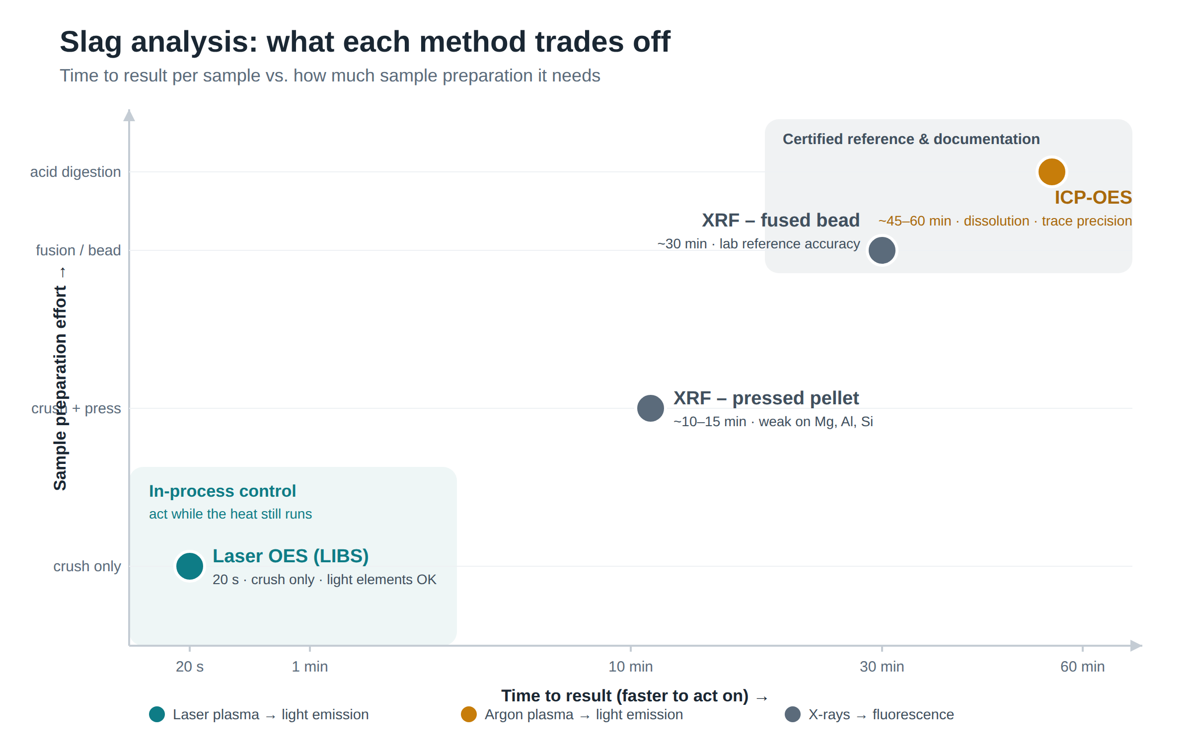
None of them is a poor method. They were designed for different tasks, and each does its own task well. The XRF fused glass bead is the reference. You melt the slag with a flux, cast a homogeneous bead, and the accuracy and reproducibility are excellent. It is the method you want behind a certificate, or in a round-robin between laboratories. The cost is time: the fusion step makes it the slowest option here.
ICP-OES sits in the same corner. To analyse slag by ICP-OES you first dissolve it, usually by acid digestion, and then measure. The accuracy reaches trace levels, which is why ICP-OES is a laboratory reference method. But the dissolution is more work still than a bead, and it takes the sample even further from the furnace.
XRF on a pressed pellet is the everyday compromise. Crush the slag, press a tablet, measure. It is robust for the major oxides. Its weak point is the light elements, magnesium, aluminium and silicon, which are sensitive to grain size and where the low penetration depth of X-rays works against the measurement. That is unfortunate, because those are often the elements slag chemistry turns on. We examined this trade-off in detail in our comparison of the fast methods.
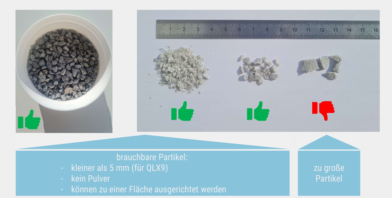
Laser OES is the method we built for the plant floor. Crush the granular slag, dose it, measure in about 20 seconds. No fusion, no dissolution, and the light elements are handled well. It runs near the line, next to the furnace, operated by the shift team.
I should be equally clear about the limits of my own method. Slag calibration for Laser OES today rests mostly on secondary and internal reference materials rather than certified CRMs, so it belongs first in process monitoring, not in certification. It is also the younger method, still establishing itself. I would rather state that plainly, which is also why we keep writing about why drift monitoring remains mandatory in OES.
Reproducibility, and an awkward number for XRF
This is the part that tends to surprise people. It surprised us as well, the first time we put the numbers side by side. "XRF is the gold standard" is true, but only for the fused bead, and only under ideal laboratory conditions. Measure a pressed pellet against a laser on real, unprepared slag, and the picture changes.
Across repeated measurement series at customer sites, XRF on pressed tablets shows a standard deviation of 0.65 % on Al₂O₃ and 0.93 % on SiO₂. The fused bead, the most labour-intensive preparation, reaches 0.26 % and 0.14 %. Laser OES, on raw granular slag, lands at 0.32 % and 0.20 %, level with the bead and far below the pressed pellet. The reproducibility table from Kardemir shows the same result on a working mill floor.
The reason is structural, not incidental. A pressed pellet is a single measuremednt on one spot of a surface assumed to be homogeneous. Laser OES fires thousands of pulses across the grains and averages them, homogenising the sample in software rather than in the preparation room. The method that does less preparation ends up more representative, in part precisely because it omits that preparation.

Speed is not the main point
The conclusion most people draw from "20 seconds" is speed. That is not really where the value sits. The value is that a measurement of 20 seconds is inexpensive enough to run often. And it is frequency, not speed in itself, that changes what happens in the plant.
Consider the two cases. In the slow one you take a single slag sample per shift, perhaps one per heat, it goes to the laboratory, and the result returns 15 to 20 minutes later, describing a slag that no longer exists. That is not process control; it is a post-mortem.
In the fast one you take three or four samples across a single heat and see them return while the heat is still running. You now have a trajectory rather than one point. FeO rising, and you reduce the oxygen. MgO drifting, and you add dololime. Basicity moving out of range, caught before it becomes a bad heat. The EAF slag deep-dive follows how these levers are coupled.
That is where the money sits. Better FeO control keeps iron in the steel rather than in the slag pot. Tighter basicity means the flux you add is the flux the slag needs, not a safety margin added because the composition is unknown. Staying within the MgO window extends refractory life. The one publicly documented figure, 0.71 € per ton of liquid steel on the ladle side, comes from the ArcelorMittal work, and the furnace side is of the same order. We put numbers to the hidden costs in False Savings in Melt Shop Slag Management.
None of this follows from replacing one slow sample with one fast sample. It follows from measuring often enough to steer. Speed is simply what makes that frequency affordable.
So, XRF or Laser OES?
Back to that call. My answer is almost never "Laser OES instead of XRF."
If the number has to stand as a certificate, a round-robin or a trace-level specification, keep the fused bead XRF and the ICP. They have earned their place, and a faster method is no reason to discard them.
If the number exists to run the heat while you can still act on it, that is the emission family, and on the floor it means Laser OES near the line. Seconds rather than minutes, several samples per heat rather than one per shift, the light elements handled.
This is not an isolated view. Fraunhofer measured Laser OES on hot slag in the pot in 2014. Swerim built a near-the-line system and calibrated it against XRF. Tenova field-tested one at two mills. Different groups, different starting points, the same conclusion. We stand in that line with the QLX9, now installed at nine mills across BOF, EAF and LF, not ahead of it. Plants such as Pittini in Verona already run it this way, for yield and for ladle life.
So when that call comes, the honest answer is usually that it is not a choice between the two. Keep the XRF for the documentation, add the fast method for the process. And the question then changes: no longer which of the three, but the one that actually governs the result, how often, within a single heat, you can afford to look.
Alexander Schlemminger
Managing Director, QuantoLux Innovation. Writes Elemental Insights on slag chemistry and melt-shop economics.
Book a 20-minute call LinkedIn · More articlesReferences
- Cremers, D.A., Radziemski, L.J., Handbook of Laser-Induced Breakdown Spectroscopy, Wiley.
- QuantoLux Innovation GmbH, QLX9 commissioning and reproducibility reports; nine steel mill customer references (2024–2026).
- Picon, A., et al., "Ladle Furnace Slag Characterization Through Hyperspectral Reflectance Regression Model for Secondary Metallurgy Process Optimization," IEEE Transactions on Industrial Informatics (2017/2018). doi.org/10.1109/TII.2017.2773068
- Sturm, V., et al., "Laser-Induced Breakdown Spectroscopy for 24/7 Automatic Liquid Slag Analysis at a Steel Works," Analytical Chemistry 86(19), 9687–9692 (2014). doi.org/10.1021/ac5022425
- Petersson, J., Gilbert-Gatty, M., Bengtson, A., "Rapid chemical analysis of steel slag by laser-induced breakdown spectroscopy for near-the-line applications," J. Anal. At. Spectrom. 35(9), 1848–1858 (2020). doi.org/10.1039/D0JA00188K
- Nakayama, K., "Glass Bead Sample Preparation for XRF," Encyclopedia of Analytical Chemistry, Wiley.